

Reactor Electric Heater Maker: Engineering Reliable Thermal Solutions for Industry
2026-08-27
Industrial thermal management rarely forgives shortcuts. A reactor electric heater that underperforms doesn't just waste energy—it can choke production, risk operator safety, and silently drain profitability. In this post, we're examining how Shenzhou Chemical Industry tackles that challenge differently: by treating every heating solution as a custom-engineered system, not a catalog item. What makes their approach worth your attention? Let's start with the failure points most manufacturers overlook.
Precision heat that holds a reactor at setpoint
The heating system keeps the reactor from drifting by constantly comparing the actual temperature against the target value. Instead of simply switching on and off, it modulates power in small, rapid increments, so the thermal mass never gets pushed too far in either direction. A sudden change in ambient conditions or a slight variation in feed flow is corrected within seconds, leaving the setpoint undisturbed.
What makes this approach stand out is how it handles the natural lag between applying heat and sensing the result. The control logic learns from the reactor's own response pattern—how quickly it warms, where it tends to overshoot, and how much heat it loses to the surroundings. That learned behavior allows the heater to anticipate rather than react, holding the temperature steady even when the process throws a curveball.
In practice, this means an exothermic spike during a reaction doesn't turn into a runaway temperature rise, and a cooling step doesn't cause the heater to overcompensate. The heat input is metered with enough precision that the reactor sits flat on its target, often within a fraction of a degree, for hours at a time. That level of stability frees operators from manual adjustments and lets the chemistry proceed exactly as intended.
Heaters that survive aggressive process fluids
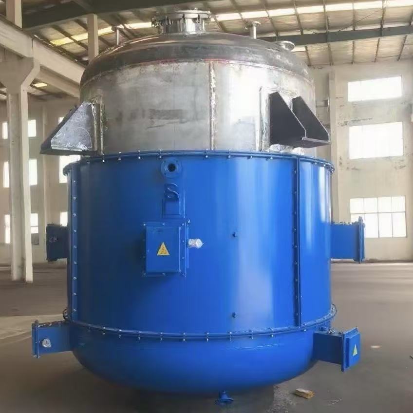
Real-world process heaters often face corrosive fluids that chew through standard stainless steel in a matter of months. For those applications, material selection matters more than watt density. Incoloy 800 and 825 sheaths handle mild acids and chlorides well, but aggressive hydrochloric or sulfuric acid streams call for PTFE-encapsulated elements or silicon carbide. The key is matching the sheath material to the specific chemical blend, not just the temperature.
Coating adhesion and seam integrity determine survival. A fluoropolymer coating with a pinhole will let acid reach the metal substrate and cause rapid failure. Look for heaters with welded, passivated seams and thick, void-free polymer layers. Ceramic or quartz sheaths are another route when organic solvents are present, since they offer near-universal chemical resistance without leaching.
Beyond materials, heater geometry can reduce localized attack. Lower watt densities spread heat across more surface area, avoiding boiling at the sheath that concentrates corrosive salts. Baffled or helical designs keep fluid moving and prevent stagnant pockets where pitting thrives. Suppliers who understand both electrochemistry and heat transfer tend to produce elements that outlast generic counterparts by years.
Why uniform watt density changes everything
Most heating elements fail not because they stop producing heat, but because they produce it unevenly. A coil wound with inconsistent spacing or a thin spot in the resistance wire creates zones that run hotter than intended. Those hot spots accelerate oxidation, cause thermal fatigue, and eventually burn out the element long before its rated life. Uniform watt density attacks that problem at the source. By distributing the electrical load evenly along the entire heated length, every square inch of the sheath works at the same temperature. There is no single point doing too much work, so the element does not destroy itself from the inside out.
That evenness also changes how the heater interacts with the material around it. In a platen, mold, or tank, uneven watt density forces you to compensate—overheating one area to get another up to temperature, or adding extra sensors and tuning to manage the swings. With a uniform profile, the part reaches setpoint more predictably, and the temperature gradient across the surface shrinks. This means fewer rejected parts, less thermal stress on the tooling, and longer intervals between replacements. For maintenance teams, it translates to fewer midnight calls and less downtime spent guessing which zone is failing.
Custom geometries, from coiled to cast-in
Most pipelines settle for straight tubes and standard elbows, but real systems rarely fit so neatly. Coiled geometries offer a compact way to handle thermal expansion or to fit long lengths into tight equipment skids, and the winding process itself can introduce subtle variations in wall thickness that actually improve fatigue resistance under cyclic loads. Cast-in configurations push this further—pouring metal or polymer directly around a pre-shaped core allows transitions, branches, and oddly angled sections to emerge as a single continuous piece, eliminating weld seams where corrosion and stress concentrations typically start.
Choosing between coiled and cast-in often comes down to how much the geometry has to fight its environment. A coil might be the right call when you need a spring-like give between two flanges that shift slightly with temperature, while a cast-in bend makes sense when the path has to weave through structural members and still meet a strict pressure rating. The tooling for cast-in can be expensive up front, but the long-term payoff shows up in fewer leak points and less inspection time on site.
What gets overlooked is how custom geometries change the way operators interact with the system. A coiled section, for instance, can act as a natural drain loop or a trap for unwanted vibration. A cast-in manifold, on the other hand, might consolidate six separate fittings into one block, simplifying both assembly and future maintenance. In practice, the geometry isn't just a shape—it becomes part of the system's behavior, and that's worth designing for rather than accepting off-the-shelf limits.
Thermal calculations before the first weld
Before striking the first arc, thermal calculations map out how heat will flow through the joint and surrounding base metal. This step is not a formality—it determines whether the weld will hold under service loads or crack from uneven cooling. By estimating peak temperatures, cooling rates, and the width of the heat-affected zone, you can anticipate distortion, residual stress, and microstructural changes that quietly weaken the finished assembly.
A practical approach starts with the heat input per unit length, calculated from arc voltage, current, and travel speed. From there, you can model the temperature field using simplified analytical solutions or finite element software. The goal is to identify areas where the cooling rate becomes too fast for the material, leading to brittle martensite in steels or excessive hardening in aluminum alloys. Adjusting preheat temperature, interpass temperature, or welding sequence often brings the thermal profile back into a safe window.
These calculations also inform the choice of filler metal and shielding gas, since both interact with the thermal cycle. For thick sections or highly restrained joints, running a thermal check before welding can reveal the need for post-weld heat treatment or a different joint design altogether. Skipping this stage might save an hour in the office, but it frequently costs days in rework, cracking, or unexpected distortion on the shop floor.
Field reports from plants that switched
At a plastics extrusion plant outside Akron, the switch to the new tension controllers initially threw off the line operators. They'd been running the old analog dials for nearly a decade, and the touchscreen interface buried the one adjustment they used most. A floor supervisor eventually mapped that function to a physical keypad shortcut, and scrap rates fell back to baseline within three shifts. The maintenance log shows no unplanned downtime in the following month, which the plant engineer attributes to fewer moving parts in the replacement units.
A dairy processing facility in central California reported a different snag: the new variable-frequency drives ran quieter, but the reduced fan noise made a previously unnoticed bearing squeal audible from the mezzanine. That turned out to be a failing conveyor roller that would have likely seized during a night run. The switch didn't cause the problem, but it changed the acoustic environment enough for the crew to catch it early.
In a third report, a metal stamping plant switched lubricant suppliers after a cost review, and the first two weeks brought a slight increase in die wear on one high-volume line. The field report notes that the issue wasn't the lubricant itself, but the changeover procedure: the line was not fully purged of the old product before the new one was introduced. Once the mixing was eliminated, die life returned to normal and the facility kept the new supplier for the lower price point.
FAQ
They focus on flanged immersion heaters, circulation heaters, and custom-designed bundles that fit directly into reactor vessels. Many units include integrated control panels and thermocouples, so the heating and temperature monitoring work as one system rather than separate bolt-ons.
Mostly chemical processing, pharmaceutical production, food and beverage, and specialty materials. Anywhere a reactor needs precise, repeatable heat—polymerization, mixing, distillation, or catalytic reactions—these heaters show up. It is less about one sector and more about processes that cannot tolerate temperature swings.
Material selection drives the design. They use stainless steel alloys, Incoloy, Hastelloy, or titanium depending on the chemistry inside the vessel. Flange ratings and element sheath thickness are matched to the operating pressure and temperature, and the design is checked against ASME or PED requirements when needed.
Yes. Explosion-proof terminal enclosures and ATEX/IECEx certified designs are available. The wiring chambers are sealed and the element cold zones are engineered so surface temperatures stay below the auto-ignition point of the surrounding gases or vapors.
It comes down to thermal design margin and avoiding hotspots. They calculate watt density against fluid viscosity and flow, specify thicker sheath walls for high-temperature service, and sometimes derate elements slightly. That sacrifices a little speed but prevents premature failure and coking on the element surface.
Often yes. If you can supply the vessel nozzle size, flange standard, existing wattage, and process conditions, they can reverse-engineer a drop-in replacement. Sometimes they suggest a revised watt density or better sheath alloy if the original unit had a short service life.
Standard flanged heaters may ship in two to four weeks. Truly custom units with exotic alloys, multiple circuits, or hazardous-area certification usually run six to ten weeks. Rush service is possible, but it depends on material availability and testing requirements.
Conclusion
When a reactor drifts even a few degrees, batch quality suffers, so a heater that holds setpoint without constant correction matters. Our approach pairs tightly wound resistance elements with sensors placed where the thermal gradient actually lives, not where it's convenient. That means fewer overshoots and less dependence on aggressive PID tuning. The sheath materials aren't chosen from a catalog—they're selected after reviewing the exact chemistry that will touch them, whether it's hot sulfuric acid, chlorinated solvents, or abrasive slurries. Passivation layers, alloy composition, and weld geometry all change depending on what the heater will face over a five-year run. We've also learned that uniform watt density is the quiet factor nobody budgets for until a hot spot takes a reactor offline. By controlling the spacing of the resistance wire and the cross-section of the sheath, we avoid the localized boiling and carbonization that plague standard designs.
Geometry is where most heater suppliers hit a wall. Standard immersion bundles don't fit odd nozzle angles, and cast-in designs often sacrifice serviceability. We start from the reactor drawing: sometimes the right answer is a coiled tubular element that snakes around a baffle; other times it's a cast aluminum or bronze plate that becomes part of the vessel wall. Before any metal is cut, we run thermal calculations—heat flux at the sheath surface, film temperature of the process fluid, and predicted fouling over months of operation. That step has caught issues a prototype would have missed. The payoff shows up in field reports. One fine chemical plant swapped a competitor's heater for ours and stopped seeing the coking that forced monthly cleanings. Another operation running exothermic polymerization held batch temperature within +/-0.3°C for six consecutive campaigns. Those outcomes don't come from marketing; they come from treating the heater as an engineered component of the reaction, not an off-the-shelf accessory.
Contact Us
Contact Person: Mr. Wang
Email: [email protected]
Tel/WhatsApp: 8613705299955
Website: https://vip.e-baixing.com/szhgyw