

Top 10 Gantry Barrel Zinc Plating Equipment for Enhanced Corrosion Resistance
2026-08-26
Corrosion doesn’t announce itself—it quietly eats into your parts, your reputation, and your bottom line. That’s why choosing the right gantry barrel zinc plating equipment matters more than most plating shops admit. But not every line claiming “enhanced corrosion resistance” delivers once it’s running three shifts a day. In this guide, we break down the top 10 systems that actually hold up in real-world conditions, from barrel rotation control to anode placement and rinse efficiency. Along the way, you’ll see why experienced operators keep turning to brands like Junda for consistent, low-maintenance performance. Here’s what made the cut—and what to look for before you invest.
Getting the Barrel Speed Right for Even Zinc Coverage
Getting the rotation rate right is less about hitting a single ideal number and more about matching the barrel diameter, part geometry, and load size. In a barrel that spins too slowly, parts spend too long buried, so the zinc deposit builds unevenly on exposed surfaces while recessed areas stay starved. A sluggish barrel also encourages gas blanketing, where hydrogen bubbles linger in blind holes and low-current-density pockets, causing skip plating or dull patches.
An overly fast barrel, however, throws parts against the wall and reduces the time each piece spends in contact with the cathode dangler. This erratic motion can actually worsen coverage on small or delicate parts, because they tumble too violently to plate properly. A practical starting range for many zinc barrel lines is 6 to 12 revolutions per minute, but you'll want to adjust within that window based on the barrel's open area and the shape of your load. Watch for a smooth cascading motion rather than a slurry-like slide or a hard centrifugal climb.
Fine-tuning barrel speed also interacts with current density and solution flow. When you increase speed, you improve solution exchange through the perforations, which helps replenish zinc ions in tight recesses. But if the current is already high, extra agitation may simply amplify edge buildup. Make small changes—one or two rpm at a time—and check thickness distribution on a few sacrificial parts before committing to a full production run.
Why Anode Placement Changes Everything in Gantry Systems
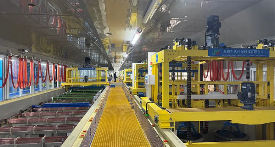
The anode in a gantry system isn't just a passive component; its position dictates how evenly current distributes across the workpiece. When placed too close to one side, you'll see uneven plating thickness, with edges burning while recessed areas starve for ions. This happens because the electric field lines bend toward the nearest anode surface, creating hotspots that no amount of bath agitation can completely fix.
Shifting the anode further back or angling it slightly changes the field geometry entirely. A well-positioned anode spreads the current density into a smoother gradient, which means fewer rejects from pitting or dull patches. In hard chrome plating lines, for instance, operators often adjust anode distance after the first trial run—a tweak of just a few centimeters can turn a cloudy deposit into a mirror finish.
Beyond thickness, anode placement also affects bath life and maintenance frequency. If anodes sit too close to the tank walls, metal builds up there and sloughs off irregularly, contaminating the solution. By moving them inward and spacing them symmetrically, you reduce sludge formation and make anode replacement less frequent. It's a small change in setup that pays off in lower chemical costs and less downtime.
Choosing Perforation Sizes That Prevent Shadowing and Improve Deposit
Getting the hole size right is less about matching a standard chart and more about how the perforation interacts with your specific material thickness and plating chemistry. If the opening is too small for the plate thickness, the sidewalls end up blocking line-of-sight current flow, creating dark, low-deposit zones near the base of each hole. If the opening is too large, you lose the shadowing control that helps keep deposit thickness even around the rim.
A practical starting point is to keep the material thickness equal to or slightly less than the hole diameter for fine-feature work. Once the thickness-to-diameter ratio climbs above roughly 1.5:1, shadowing becomes easy to spot in cross-sections as thin or missing plating near the center of the perforation. Edge-to-edge spacing matters just as much; leaving at least one hole diameter between adjacent perforations prevents the electric field from bunching up and creating thicker deposit bridges between openings.
Straight-walled holes are not always the best choice, even if they are easier to produce. A slight taper or a stepped profile can reduce sidewall shadowing while still preserving deposit thickness at the rim. When in doubt, run a small pilot strip with graduated hole sizes, then inspect cross-sections under magnification. Base the final selection on measured deposit thickness variation, not just on how the holes look from the top.
How Load Size Impacts Current Distribution and Coating Thickness
In electroplating, the total surface area of parts in a single run directly reshapes how current spreads across the cathode. A larger load demands more amperage to maintain the same nominal current density, but power supplies and busbar layouts rarely deliver that increase perfectly. Edges and projections facing the anodes become current sinks while recessed zones starve, so the practical density diverges sharply from the calculated average.
This mismatch deepens because electrolyte resistance and anode-to-cathode spacing stay fixed while the workpiece cluster grows. Outer rows shield inner parts, creating a Faraday cage effect that suppresses deposition in the center of the rack. The resulting coating thickness follows a radial gradient: corners can build twice the target thickness while centers remain below specification, especially on complex geometries where current must travel through convoluted paths.
Operators typically compensate by reducing the batch size, repositioning anodes, or introducing auxiliary cathodes to bleed excess current from high-density zones. Pulse plating also helps by allowing diffusion recovery during off-cycles, smoothing thickness variation without sacrificing throughput. Ignoring load size, however, guarantees rework or scrap, as the final film distribution becomes a lottery rather than a controlled outcome.
Simple Maintenance Habits That Keep Corrosion Resistance High
Most corrosion problems start small—a scratch, a missed rinse, a bit of trapped moisture. The fix is often just as small. Wiping down stainless surfaces with a clean, dry cloth after use prevents mineral deposits from sitting overnight. In marine or industrial settings, a weekly rinse with fresh water removes salt and chemical films before they eat into the passive layer.
Pay attention to crevices and joints. These hidden spots collect water and debris, becoming corrosion hot spots long before visible rust appears. A soft brush or compressed air can clear them without scratching the surface. Avoid steel wool or harsh abrasives; they leave behind tiny iron particles that rust and break down the protective oxide film.
Finally, check protective coatings and sealants every few months. A small touch-up now prevents a costly replacement later. Keeping a simple log—when you rinsed, what you noticed, any changed areas—helps you spot patterns and catch problems while they’re still easy to fix.
What Field Testing Shows About Long-Term Performance
Accelerated lab tests can simulate heat, moisture, and UV exposure, but they rarely capture how these factors interact over years in a single installation. Field testing fills that gap by tracking actual degradation in situ. One consistent finding is that materials often fail not from a single dramatic event but from the slow accumulation of small stresses—thermal cycling at joints, micro-vibrations from nearby traffic, or repeated wet-dry transitions. These combined effects can expose weaknesses that no single-variable test would predict.
Another pattern that emerges from long-term field data is performance drift. A coating might remain intact visually yet lose significant adhesion strength after five years, or a sealant might still look flexible but no longer recover its original shape after compression. Monitoring these subtle shifts matters because they signal the point at which maintenance becomes cheaper than replacement. Field sites with consistent documentation often reveal that the first measurable decline appears much earlier than visible cracking, peeling, or corrosion, which changes how owners plan inspections.
Perhaps most useful is what field testing shows about regional variability. The same product can perform well in one climate and degrade rapidly in another, not just because of average temperature or rainfall, but because of local factors like airborne salt, industrial pollutants, or the angle and intensity of sunlight. Long-term field programs that include multiple sites help separate material limitations from installation errors. They also provide a reality check for warranty periods: a product that excels in a temperate test plot may need a revised specification for coastal or high-altitude environments.
FAQ
Rotation speed controls how parts tumble and expose fresh surfaces to the plating solution. If it is too slow, parts nest together and create shadowed areas with almost no zinc. Too fast, and you get abrasion that strips the coating before it fully forms. Most gantry barrel lines run best between 4 and 10 rpm, but you need to adjust based on part shape and barrel diameter. A quick test with test coupons can reveal the sweet spot before you commit to a full production run.
Start with the dangler contacts and barrel perforations. Worn dangler tips cause erratic current flow, which leads to burnt edges or thin patches. Clogged perforations starve the barrel interior of fresh solution, so parts in the center come out with powdery or dull zinc. Also check tank liners for blisters and anode baskets for bridging. These simple checks take fifteen minutes but can stop a lot of corrosion-related rejects.
Mixing sizes and shapes is always a compromise. The best approach is to group parts by surface area and avoid loading heavy stampings with tiny fasteners in the same barrel. If you must mix, add inert media or dummy parts to keep the load moving and prevent nesting. Also reduce the load volume to about fifty percent of barrel capacity, which gives every part enough room to tumble and receive a complete zinc layer.
The solution inside the barrel gets depleted much faster than the main tank because the perforations restrict flow. A tank sample might show normal zinc and brightener levels while the barrel interior is starved. To get true readings, draw a sample from inside the barrel during plating and test that. Then adjust additions based on the barrel sample, not the tank sample. Otherwise you will run lean and produce thin, porous coatings that corrode early.
Ripple percentage is the big one. A rectifier with high ripple produces a spongy, porous zinc deposit that looks fine but fails salt spray quickly. Aim for less than five percent ripple. Undersizing the rectifier is another common mistake because total surface area is often underestimated. If the rectifier runs at maximum output all shift, temperature rises and output drifts. Leave at least twenty percent headroom and calibrate the current and voltage meters every quarter.
Automated transfer eliminates the timing errors that come with manual hoists. Each barrel spends exactly the same time in the plating bath, rinse, and post-treatment. That consistency prevents both under-plating from short cycles and over-pickling from extended acid dips. It also reduces physical damage to parts during transfer, so the zinc coating is not scratched or chipped before it reaches the customer. Fewer handling mistakes means fewer corrosion hot spots.
Keep a daily log of barrel drive chain tension and dangler contact wear. Replace worn dangler tips before they fail, not after a shift of rejects. Monthly, pull the anode bags and rinse them to maintain current distribution. Every three months, inspect the barrel gears and replace any cracked teeth. Also keep the gantry rails clean and level, because a wobbling barrel causes uneven plating and puts extra stress on the drive motor. These habits cost little but can add years to the line.
Conclusion
Achieving reliable corrosion resistance in gantry barrel zinc plating depends less on tank size and more on how well a handful of operating variables are controlled. Barrel rotation speed, for example, has to be dialed in for the specific part geometry; too slow and workpieces nest in the same orientation, starving some recesses of current, while too fast tumbles parts so aggressively that zinc never has a chance to settle uniformly. Anode placement works hand in hand with this. In gantry systems, the distance and angle between anodes and the barrel change as the barrel moves, so simply hanging anodes at the ends of the tank weakens coverage on the inward-facing surfaces. Adjusting anode positioning to track with the barrel’s travel path makes a measurable difference in deposit uniformity. Perforation sizing is another quiet failure point. Holes that are too small trap solution and gas, creating shadowed areas where plating thins out; oversized perforations allow small parts to wedge and block flow. Matching hole diameter to the smallest feature on the parts, and spacing perforations to encourage solution exchange, prevents most shadowing. Load size also directly dictates current distribution. A barrel packed too tightly forces more current through the outer layer of parts, leaving inner parts with thinner zinc and lower corrosion resistance, while underloading wastes energy and can cause burning on exposed edges.
Maintenance habits then decide whether that initial plating quality lasts. Regularly cleaning anode bags, checking barrel danglers for wear, and monitoring rectifier output prevents slow drift in coating thickness that field-testing often links to premature rust. Zinc anodes that crust over deliver uneven current, and loose electrical contacts create hot spots. On the maintenance side, keeping solution chemistry within a narrow range—especially pH and zinc concentration—matters more than many operators assume. Field testing across multiple gantry installations shows that equipment with consistent rotation speed, properly placed anodes, and clean perforations retains its corrosion resistance far longer than systems where these details are neglected. The best-performing lines are not necessarily the most expensive; they are the ones where operators treat barrel speed, anode geometry, perforation condition, load weight, and routine upkeep as one connected system. That integrated attention is what separates a line that passes a salt spray test for a few hundred hours from one that keeps parts rust-free for years.
Contact Us
Contact Person: hayyr
Email: [email protected]
Tel/WhatsApp: 8613082110525
Website: https://www.jundaelectroplating.com